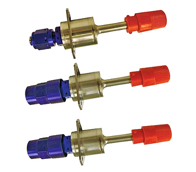
Fill, Drain & Vent Valves for Spacecraft Propulsion Systems
For propellants, pressurants and high pressure gases. Also ground half couplings.

Fill and Drain / Vent valves
Range of FDV Valves
Our wide range of Fill and Drain / Vent valves (FDV) are typically used for the loading and venting functions of all kinds of
propellants, pressurants and propellant vapours.
All valves in the range are space qualified and fulfill the requirements for either two or three mechanical inhibits against
leakage . The valves can also be used for test port functions.
Valve Types
Six different valves types are available, each providing a different interface to prevent misconnection at spacecraft level.
These types differ mainly in thread size and orientation.
Propellant loading and venting valves are designed to provide three independent inhibits, while gas type or test port valves
provide 2 independent inhibits.
Propellant and test port FDV's provide excellent compatibility with storable propellants such as MMH, Hydrazine, MON- 1 as well
as MON-3.
Special high pressure gas type FDV's are available for operation with Helium (He) and Xenon (Xe). In general all types are
compatible with standard test agents (IPA / HFE 7100 / deionized water) and gases (He, N2).
Design Features
The following design attributes and features are common to all six types of FDV :
- All piece parts of the valve are machined from titanium alloy (Ti6Al4V) leading to a light weight unit with 0.25
inch/ 6.4mm outlet diameter tube stub which forms a weldable connection to the titanium tubing of the subsystem
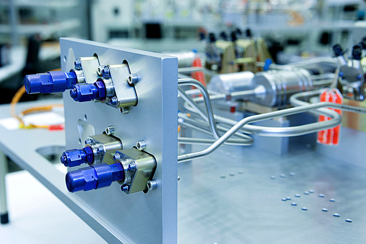
- The interface to the subsystem structure is provided by a triangular flange with triple-screw attachment (thread
size M4)
- An all welded housing containing a spring supported guided valve poppet equipped with the primary seal. This
ensures that the valve is kept closed in non actuated conditions.
- In flight configuration the valve poppet sealing will be additionally protected and sealed by mounting a cap,
thus providing a metal-to-metal seal (secondary seal).
- Low pressure drop even at high mass flows ensured by design. The flow area is at least as large as the connected
tubing

Ground Half Coupling
Ground Half Coupling
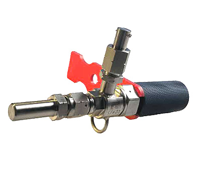
For servicing, a dedicated Ground Half Coupling (GHC) is required. For each FDV type there is a respective GHC permitting only
mating of the correct type. By this means a safe and easy to handle, leak-tight connection between the propulsion system and the
ground support equeipmnt is guaranteed.
Each GHC provides a robust specific opening / closing mechanism to safely operate the FDV. No specific tooling is required.
Main Features
- Actuation of FDV is made by manually operated pin.
- No generation of particles during opening and closing of the valve poppet.
- Easy monitoring of valve status (red safety clamp can be inserted in the closed position of the valve).
- Ground half coupling with bypass available for safe handling of toxic media.
- High compatibility with media due to the materials selected.
- Low pressure drop across the valve.

Integrated fill and drain valves
FDV Valve Characteristics
The characteristics of each off-the-shelf fill, drain and vent valve is shown below:
Operating Media
Monomethyl Hydrazine (MMH)
Standard Tube Dimensions
- outer diameter
- inner diameter
6.4 ± 0.02mm
5.58 + 0.11 mm
Adapter Thread
9/16" - 18 UNJF - 3A - RH. Requires
corresponding ground half coupling
Life
- Operational Life
- Storage Life
About 16 years
Up to 5 years in a protected environment
Open/Close Cycles
40 Cycles
Standard Operating Temp.
243 to 353 K
Leakage
- external Leakage
- internal Leakage
< 1x10⁻⁶ scc/sec GHe
< 2.8x10⁻⁴ scc/sec GHe
Operating Media
Monomethyl Hydrazine (MMH)
Total Length
112.5 ± 1 mm
Standard Tube Dimensions
- outer diameter
- inner diameter
6.4 ± 0.02mm
5.58 + 0.11 mm
Adapter Thread
7/16" - 20 UNJF - 3A - RH. Requires
corresponding ground half coupling
Life
- Operational Life
- Storage Life
About 16 years
Up to 5 years in a protected environment
Open/Close Cycles
40 Cycles
Standard Operating Temp.
243 to 353 K
Leakage
- external Leakage
- internal Leakage
< 1x10⁻⁶ scc/sec GHe
< 2.8x10⁻⁴ scc/sec GHe
Operating Media
Nitrogen Tetroxide (MON)
Standard Tube Dimensions
- outer diameter
- inner diameter
6.4 ± 0.02mm
5.58 + 0.11 mm
Adapter Thread
9/16" - 18 UNJF - 3A - LH. Requires
corresponding ground half coupling
Life
- Operational Life
- Storage Life
About 16 years
Up to 5 years in a protected environment
Open/Close Cycles
40 Cycles
Standard Operating Temp.
243 to 353 K
Leakage
- external Leakage
- internal Leakage
< 1x10⁻⁶ scc/sec GHe
< 2.8x10⁻⁴ scc/sec GHe
Operating Media
Nitrogen Tetroxide (MON)
Total Length
112.5 ± 1 mm
Standard Tube Dimensions
- outer diameter
- inner diameter
6.4 ± 0.02mm
5.58 + 0.11 mm
Adapter Thread
7/16" - 20 UNJF - 3A - LH. Requires
corresponding ground half coupling
Life
- Operational Life
- Storage Life
About 16 years
Up to 5 years in a protected environment
Open/Close Cycles
40 Cycles
Standard Operating Temp.
243 to 353 K
Leakage
- external Leakage
- internal Leakage
< 1x10⁻⁶ scc/sec GHe
< 2.8x10⁻⁴ scc/sec GHe
Operating Media
Helium (High Pressure)
Total Length
112.5 ± 1 mm
Standard Tube Dimensions
- outer diameter
- inner diameter
6.4 ± 0.02 mm
4.9 + 0.1 mm
Adapter Thread
M 12 x 1.5 - RH. Requires
corresponding ground half coupling
Life
- Operational Life
- Storage Life
About 16 years
Up to 5 years in a protected environment
Open/Close Cycles
40 Cycles
Standard Operating Temp.
243 to 353 K
Leakage
- external Leakage
- internal Leakage
< 1x10⁻⁶ scc/sec GHe
< 2.8x10⁻⁴ scc/sec GHe
Operating Media
Xenon (High Pressure)
Standard Tube Dimensions
- outer diameter
- inner diameter
6.4 ± 0.02 mm
4,9 + 0.1 mm
Adapter Thread
M 14 x 1.5 - RH. Requires
corresponding ground half coupling
Life
- Operational Life
- Storage Life
About 16 years
Up to 5 years in a protected environment
Open/Close Cycles
40 Cycles
Standard Operating Temp.
243 to 353 K
Leakage
- external Leakage
- internal Leakage
< 1x10⁻⁶ scc/sec GHe
< 2.8x10⁻⁴ scc/sec GHe
Operating Media
Various fluids
(Propellants and Pressurants)
Standard Tube Dimensions
- outer diameter
- inner diameter
- inner diameter (at weld i/f)
6.4 ± 0.02mm
4.9 + 0.01mm
5.58 ± 0.02mm
Adapter Thread
Fuel Loading 9/16" - 18 UNJF - 3A - RH.
Fuel Venting 7/16" - 20 UNJF - 3A - RH.
Ox Loading 9/16" - 18 UNJF - 3A - LH.
Ox Venting 7/16" - 20 UNJF - 3A - LH.
Note: All of the above threads require
corresponding ground half couplings
Life
- Operational Life
- Storage Life
About 16 years
Up to 5 years in a protected environment
Open/Close Cycles
40 Cycles
Standard Operating Temp.
243 to 353 K
MEOP
- Fuel / Ox Loading / Venting
Up to 33 bar
Leakage
- external Leakage
- internal Leakage
< 1x10⁻⁶ scc/s GHe
< 2.8x10⁻⁴ scc/s GHe
Sinusoidal Vibration
Up to 20 g
Random Vibration
Up to 5 g²/Hz (56.3g RMS)
Pyrotechnic Shock
Up to 3250 g
Heritage
Since their original qualification in 1983, thousands of fill, drain and vent valves have been produced and delivered for a
variety of spacecraft programmes including Eutelsat W3A, Amazonas, Inmarsat 4 F1, Anik F3, Skynet 5A, Skynet 5B, Amos 2, Astar, Star
1, Galaxy 17, Hispasat, MSG-4, Microsats, Herschel Planck, Pleiades, Spacebus, Eurostar communication satellites, Mars Express, Venus
Express and ESA's Automated Transfer Vehicle.

|
Fluidic Equipment
(PDF Brochure)
|
Fluidic Equipment Brochure (pdf)
This brochure is available to
view online from where it may be
downloaded.
Get the latest version of the free Adobe Acrobat Reader

If you require the printed version of this brochure, or more detailed information about this product please
contact us.
See the complete list of our space propulsion brochures
available for download.


